Telecom is the transmission of signals over long distances. It began with the invention of the telegraph in 1837, followed by the telephone in 1876. Radio broadcasts began in late 1800s and the first television broadcasts started in the early 1900s. Today, popular forms of telecommunications include the Internet and cellular phone networks.
Early telecommunications transmissions used analogue signals, which were transferred over copper wires. Today, telephone and cable companies still use these same lines, though most transmissions are now digital. For this reason, most new telecommunications wiring is done with cables that are optimized for digital communication, such as fiber optic cables and digital phone lines. Since both analogue and digital communications are based on electrical signals, transmitted data is received almost instantaneously, regardless of the distance. This allows people to quickly communicate with others across the street or across the globe. So whether you're watching TV, sending an email to a co-worker, or talking on the phone with a friend, you can thank telecommunications for making it possible.
 Core Values
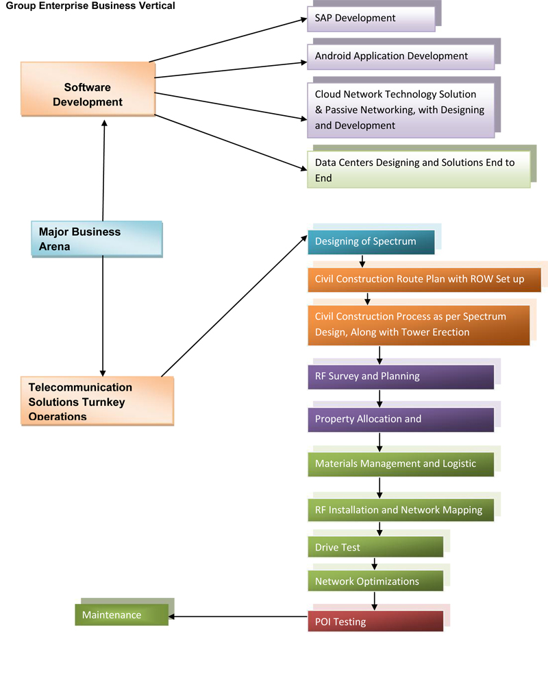
ISWPL, a fast growing leading Network Services & Infrastructure
company, offering services and solutions to address the Telecom Network Infrastructure End
to End Solution.
 Our Specified Vertical Contents End to End Telecom Service & complete Solutions, Pipe Line
Infrastructure Solutions along with trenchless and Open Trench Process on Utility Sector
Also , IT& ITES with Infrastructure Solutions etc.
ISWPL – IT Segment , is one of the growing global IT solutions and
service providers based in Delhi, India. has state-of-the arts infrastructure with solution
process of , Cloud Networking , Managed Service , Critical Software Solution with Client
recommendations , Data Center Technology and Solution . Manpower Solution
Our focus is to help the corporations create and sustain a competitive advantage. As a
committed Organization, and its customers, vendors and employees a wealth of multicultural
experience. ISWPL services allow companies to improve
corporate performance by enabling key elements in the management aspects of business.
ISWPL offers Complete solutions process with end to End on
Telecommunications from Concept towards reality stage e.g. Survey , Business forecast ,
Engineering Infrastructure Development , TI/ RF Implementation , Vendor Management
and Customer Solution As a diverse end-to-end solutions provider, we offers a range of
expertise aimed at helping customers re-engineer and re-invent their businesses to compete
successfully in an ever-changing marketplace.
We have strategic alliances with top level companies that help us provide end-to-end
services to our customers. on demand deployment of domain knowledge and technical
expertise brings to customers a range of solutions and products that enhance ROI. Our
unique engagement models allow us to leverage local competencies to offer global
competitiveness to our customers. Our consulting and IT services have resulted in latest
transformations that have been tuned to meet the international quality standards. At we
strictly practice the quality management and assurance as per the standard of ISO
9001:2008 , TL -9000
The core team is comprised of young and dynamic professionals in the field of information
technology, who has the experience in running and implementing various ERP Solutions,
Data warehousing, Industrial Automation and BPO Services for more than 10- 18 years
each.

Company involves in Telecom Vertical is a service provider
company in telecom sector where we strive to deliver
the best to our customers.
Our strength lies in our pool of experienced and highly
trained professionals.
We deliver practical and feasible solutions using
specialist test equipment’s project management
expertise.
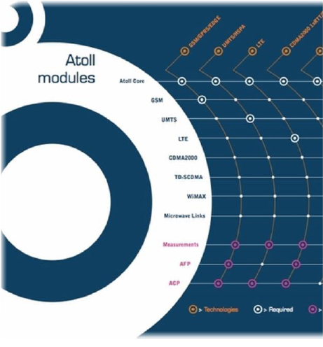
GSM UMTS CDMA SCDMA EDGE WIMAX
We offer our services to a wide range of networks such
as GSM, GPRS, EDGE, CDMA and UMTS networks, WMAX ,
including network solutions with management .
The electromagnetic spectrum is the range of all possible frequencies of electromagnetic radiation.The "electromagnetic spectrum" of an object has a different meaning, and is instead the characteristic distribution of electromagnetic radiation emitted or absorbed by that particular object.
The electromagnetic spectrum extends from below the low frequencies used for modern radio communication to gamma radiation at the short-wavelength (high-frequency) end, thereby covering wavelengths from thousands of kilometres down to a fraction of the size of an atom. The limit for long wavelengths is the size of the universe itself, while it is thought that the short wavelength limit is in the vicinity of the Planck length. Until the middle of last century it was believed by most physicists that this spectrum was infinite and continuous.
Most parts of the electromagnetic spectrum are used in science for spectroscopic and other probing interactions, as ways to study and characterize matter.In addition, radiation from various parts of the spectrum has found many other uses for communications and manufacturing (see electromagnetic radiation for more applications).
| Class | Freq- uency |
Wave- length |
Energy | ||
| γ | Gamma rays | 300 EHz | 1 pm | 1.24 MeV | |
| 30 EHz | 10 pm | 124 keV | |||
| HX | Hard X-rays | ||||
| 3 EHz | 100 pm | 12.4 keV | |||
| SX | Soft X-rays | ||||
| 300 PHz | 1 nm | 1.24 keV | |||
| 30 PHz | 10 nm | 124 eV | |||
| EUV | Extreme ultraviolet |
||||
| 3 PHz | 100 nm | 12.4 eV | |||
| NUV | Near ultraviolet |
||||
| Visible | 300 THz | 1 μm | 1.24 eV | ||
| NIR | Near infrared | ||||
| 30 THz | 10 μm | 124 meV | |||
| MIR | Mid infrared | ||||
| 3 THz | 100 μm | 12.4 meV | |||
| FIR | Far infrared | ||||
| 300 GHz | 1 mm | 1.24 meV | |||
| Micro- waves and radio waves |
EHF | Extremely high frequency |
|||
| 30 GHz | 1 cm | 124 μeV | |||
| SHF | Super high frequency |
||||
| 3 GHz | 1 dm | 12.4 μeV | |||
| UHF | Ultra high frequency |
||||
| 300 MHz | 1 m | 1.24 μeV | |||
| VHF | Very high frequency |
||||
| 30 MHz | 10 m | 124 neV | |||
| HF | High frequency |
||||
| 3 MHz | 100 m | 12.4 neV | |||
| MF | Medium frequency |
||||
| 300 kHz | 1 km | 1.24 neV | |||
| LF | Low frequency |
||||
| 30 kHz | 10 km | 124 peV | |||
| VLF | Very low frequency |
||||
| 3 kHz | 100 km | 12.4 peV | |||
| VF / ULF | Voice frequency /Ultra low frequency |
||||
| 300 Hz | 1 Mm | 1.24 peV | |||
| SLF | Super low frequency |
||||
| 30 Hz | 10 Mm | 124 feV | |||
| ELF | Extremely low frequency |
||||
| 3 Hz | 100 Mm | 12.4 feV | |||
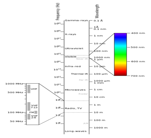
The electromagnetic spectrum
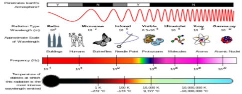
A diagram of the electromagnetic spectrum, showing various properties across the range of frequencies and wavelengths
Boundaries
A discussion of the regions (or bands or types) of the electromagnetic spectrum is given below. Note that there are no precisely defined boundaries between the bands of the electromagnetic spectrum; rather they fade into each other like the bands in a rainbow (which is the sub-spectrum of visible light). Radiation of each frequency and wavelength (or in each band) will have a mixture of properties of two regions of the spectrum that bound it. For example, red light resembles infrared radiation in that it can excite and add energy to some chemicalbonds and indeed must do so to power the chemical mechanisms responsible for photosynthesis and the working of the visualsystem.
The types of electromagnetic radiation are broadly classified into the following classes:
This classification goes in the increasing order of wavelength, which is characteristic of the type of radiation. While, in general, the classification scheme is accurate, in reality there is often some overlap between neighbouring types of electromagnetic energy. For example, SLF radio waves at 60 Hz may be received and studied by astronomers, or may be ducted along wires as electric power, although the latter is, in the strict sense, not electromagnetic radiation at all.
The distinction between X-rays and gamma rays is partly based on sources: the photons generated from nuclear decay or other nuclear and sub nuclear/particle process, are always termed gamma rays, whereas X-rays are generated by electronic transitions involving highly energetic inner atomic electrons. In general, nuclear transitions are much more energetic than electronic transitions, so gamma-rays are more energetic than X-rays, but exceptions exist. By analogy to electronic transitions, muonic atom transitions are also said to produce X-rays, even though their energy may exceed 6 megaelectronvolts (0.96 pJ), whereas there are many (77 known to be less than 10 keV (1.6 fJ)) low-energy nuclear transitions (e.g., the 7.6 eV (1.22 aJ) nuclear transition of thorium-229), and, despite being one million-fold less energetic than some muonic X-rays, the emitted photons are still called gamma rays due to their nuclear origin.
The convention that EM radiation that is known to come from the nucleus, is always called "gamma ray" radiation is the only convention that is universally respected, however. Many astronomical gamma ray sources (such as gamma ray bursts) are known to be too energetic (in both intensity and wavelength) to be of nuclear origin. Quite often, in high energy physics and in medical radiotherapy, very high energy EMR (in the >10 MeV region) which is of higher energy than any nuclear gamma ray, is not referred to as either X-ray or gamma-ray, but instead by the generic term of "high energy photons."
The region of the spectrum in which a particular observed electromagnetic radiation falls, is reference frame-dependent (due to the Doppler shift for light), so EM radiation that one observer would say is in one region of the spectrum could appear to an observer moving at a substantial fraction of the speed of light with respect to the first to be in another part of the spectrum. For example, consider the cosmic microwave background. It was produced, when matter and radiation decoupled, by the de-excitation of hydrogen atoms to the ground state. These photons were from Lyman series transitions, putting them in the ultraviolet (UV) part of the electromagnetic spectrum. Now this radiation has undergone enough cosmological red shift to put it into the microwave region of the spectrum for observers moving slowly (compared to the speed of light) with respect to the cosmos.
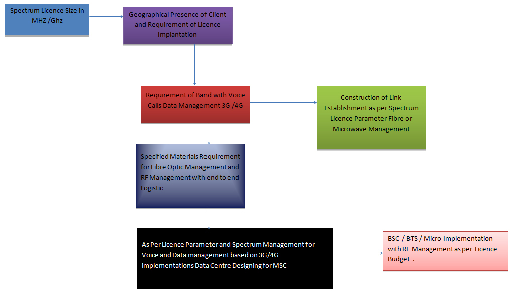
Spectrum management is the process of regulating the use of radio frequencies to promote efficient use and gain a net social benefit. The term radio spectrum typically refers to the full frequency range from 3 kHz to 300 GHz that may be used for wireless communication. Increasing demand for services such as mobile telephones and many others has required changes in the philosophy of spectrum management. Demand for wireless broadband has soared due to technological innovation, such as 3G and 4G mobile services, and the rapid expansion of wireless internet services. Since the 1930s, spectrum was assigned through administrative licensing. Limited by technology, signal interference was once considered as a major problem of spectrum use. Therefore, exclusive licensing was established to protect licensees' signals. This former practice of discrete bands licensed to groups of similar services is giving way, in many countries, to a "spectrum auction" model that is intended to speed technological innovation and improve the efficiency of spectrum use. During the experimental process of spectrum assignment, other approaches have also been carried out, namely, lotteries, unlicensed access and privatization of spectrum. Most recently, the President's Council of Advisors for Science and Technology (PCAST) advocated the sharing of (unclear) federal radio spectrum when unused at a place and time provided it does not pose undue risks. Following PCAST's recommendations, President Obama made shared spectrum the policy of the United States on 14 June 2013 Shared Spectrum. As of Dec 2014 the FCC was extending the limited success of television band spectrum sharing (TV white space) into other bands, significantly into the 3550-3700 MHz US Navy radar band via a three tier licensing model (incumbent, priority, and general access) while Europe has been pursuing an authorized shared access (ASA) licensing.
| ITU radio bands | ||||||||||||
|
In addition to our services we provide values such as zero waiting time for
kit replacement, 24 hours ready bench strength for emergency resource
Replacement during the projects.
Covering the entire value chain, we have gained the confidence of our
Customers by delivering projects with complete reliability. skilled and experienced
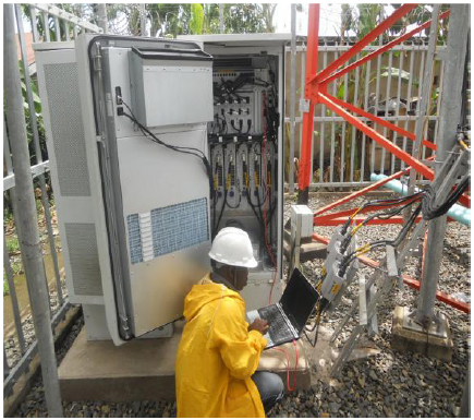
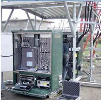
Construction Engineers , BTS, RF engineers, Optimizers, Planners, Project
Coordinators and Projects Managers which is committed to deliver the best to
our customers.

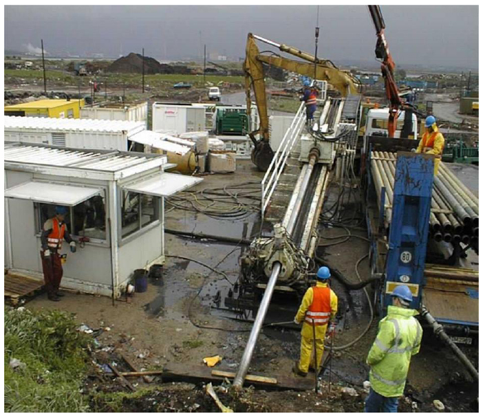
The tools and techniques used in the horizontal directional drilling (HDD) process are an Outgrowth of the oil well drilling industry. The components of a horizontal drilling rig used for Pipeline constructions are similar to those of an oil well drilling rig with the major exception being That a horizontal drilling rig is equipped with an inclined ramp as opposed to a vertical mast. HDD Pilot hole operations are not unlike those involved in drilling a directional oil well. Drill pipe and Down hole tools are generally interchangeable and drilling fluid is used throughout the operation to Transport drilled spoil, reduce friction, stabilize the hole, etc.
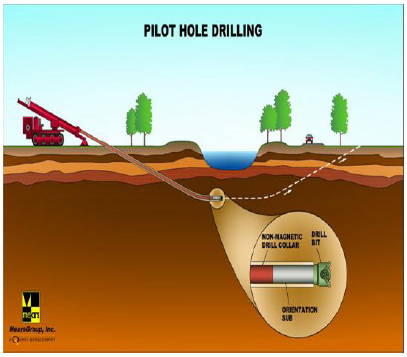
Pilot hole directional control is achieved by using a nonrotating drill string with an asymmetrical leading edge. The asymmetry of the leading edge creates a steering bias while the nonrotating aspect of the drill string allows the steering bias to be held in a specific position while drilling. If a change in direction is required, the drill string is rolled so that the direction of bias is the same as the desired change in direction. The direction of bias is referred to as the tool face. Straight progress may be achieved by drilling with a series of offsetting tool face positions. The drill string may also be continually rotated where directional control is not required. Leading edge asymmetry can be accomplished by several methods.
Downhole mechanical
cutting action required
for harder soils is
provided by down hole
hydraulic
motors. Downhole
hydraulic motors,
commonly referred to
as mud motors, convert
hydraulic
energy from drilling
mud pumped from the
surface to mechanical
energy at the bit. This
allows for
bit rotation without drill
string rotation. There
are two basic types of
mud motors; positive
displacement and
turbine. Positive
displacement motors
are typically used in
HDD applications.
Basically, a positive
displacement mud
motor consists of a
spiral-shaped stator
containing a
sinusoidal shaped
rotor. Mud flow through
the stator imparts
rotation to the rotor
which is in turn
connected through a
linkage to the bit.
In some cases, a larger
diameter wash pipe
may be rotated
concentrically over the
non-rotating
steerable drill string.
This serves to prevent
sticking of the steerable
string and allows its
tool face
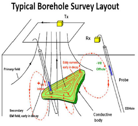
The actual path of the pilot hole Down hole Surveying –
is monitored during drilling by
taking periodic readings of the
inclination and azimuth of the
leading edge. Readings are
taken with an instrument,
commonly
referred to as a probe, inserted
in a drill collar as close as
possible to the drill bit.
Transmission of
down hole probe survey
readings to the surface is
generally accomplished through
a wire running
inside the drill string. These
readings, in conjunction with
measurements of the distance
drilled
since the last survey, are used to
calculate the horizontal and
vertical coordinates along the
pilot hole relative to the initial
entry point on the surface
Azimuth readings are taken from
the earth's magnetic field and
are subject to interference from
down hole tools, drill pipe, and
magnetic fields created by
adjacent structures.
Therefore, the probe must be
inserted in a non magnetic collar
and positioned in the string so
that it is Adequately isolated
from downhole tools and drill
pipe. The combination of bit,
mud motor (if used), subs,
survey probe, and non magnetic
collars is referred to as the
Bottom Hole Assembly or BHA.
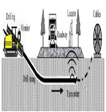
The pilot hole path may also be tracked using a surface monitoring system. Surface monitoring systems determine the location of the probe down hole by taking measurements from a grid or point on the surface. An example of this is the TruTracker System. This system uses a surface coil of known location to induce a magnetic field. The probe senses its location relative to this induced magnetic field and communicates this information to the surface.
Reaming & Pullback
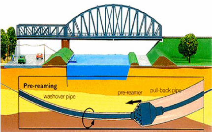
Enlarging the pilot hole is accomplished using either pre-reaming passes prior to pipe installation or simultaneously during pipe installation. Reaming tools typically consist of a circular array of cutters and drilling fluid jets and are often custom made by contractors for a particular hole size or type of soil. Pre-Reaming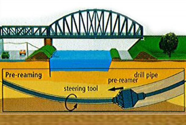
Most contractors will opt to pre-ream a pilot hole before attempting to install pipe. For a Pre-reaming pass, reamers attached to the drill string at the exit point are rotated and drawn to the drilling rig thus enlarging the pilot hole. Drill pipe is added behind the reamers as they progress toward the drill rig. This insures that a string of pipe is always maintained in the drilled hole. It is also possible to ream away from the drill rig. In this case, reamers fitted into the drill string at the rig are rotated and thrust away from it
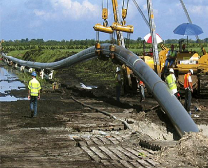
Pipe installation is accomplished by attaching the prefabricated pipeline pull section behind a reaming assembly at the exit point and pulling the reaming assembly and pull section back to the drilling rig. This is undertaken after completion of pre-reaming or, for smaller diameter lines in soft soils, directly after completion of the pilot hole. A swivel is utilized to connect the pull section to the leading reaming assembly to minimize torsion transmitted to the pipe. The pull section is supported using some combination of roller stands, pipe handling equipment, or a flotation ditch to minimize tension and prevent damage to the pipe.
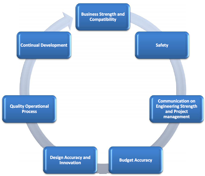
Customer Satisfaction Moto
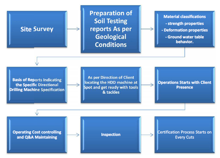
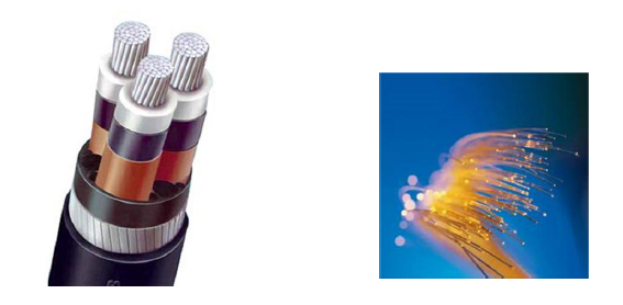
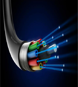
ISWPL portfolio of telecom services has prepared this profile specifically to meet the up coming needs of your esteemed organization which provides tailored solution based on our customer requirements. We plan, deploy and manage your optical networks covering project management, operational support, customer care management, systems integration, value added service platforms and Competence Solutions. Optical Fiber Implementation (OFI) is ISWPL Telecommunication Division’s core business. OFI is a standalone service, meaning it can be purchased independent of full project management (roll-out management).

We provide turnkey solutions in
all activities of Outside Plant
Works. Our services start right
from design through construction
and commissioning of optical
networks.
Scope of Optical Fiber Cable
Works includes the following:-
Route Survey, Total Design, Row
permissions, Trenching and
associated Civil works, Horizontal
Directional Drilling & Boring
works, Supply, Installation &
Commissioning of i) HDPE, GI,
RCC, DWC & PVC Pipes ii) Cables
(OF & Cu), Splice Closures, FMS,
Optical network equipment,
Electronic route markers iii) RCC
markers, Chambers, Manholes,
Hand Holes, Splicing of Cables,
Earthing and Link Testing, Asbuilds
and Operation &
Maintenance of OFC equipments
& Cables
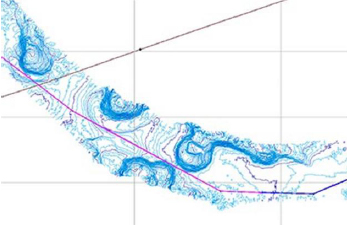

Excavation of Trenches
Standard depth of trench
will be as per
specifications Outside
the city limits trench will
normally follow boundary
of roadside land.
However, where road
side land is full of borrow
pits or forestation, or
when cable is to be laid
along Culverts/bridges or
cross-streams, trench
may be made closer to
road edge or in some
cases, over
embankment or shoulder
of the road.
Line up of trench would
be such that HDPE
duct(s) will be laid in
straight line, both
laterally as well as
vertically except at
locations where it has to
necessarily take a bend
because of change in
alignment or gradient of
trench. Minimum radius
of two meters will be
maintained, where
bends are necessitated
| S. no. | Machinery Details | Make / Model | Industry | Number | Remarks |
| 1 | Splicing Machine | Fujicora | Telecom | 2 | Own |
| 2 | OTDR | FLUKE | Telecom | 2 | Own |
| 3 | Digital Camera | Cannon | Telecom | 3 | Own |
| 4 | Toolkits | Huawai | Telecom | 4 | Own |
| 5 | HDD Trenchless | Drillto | Telecom & Utility | 3 | Contract |
| 6 | Laptop | Toshiba | Telecom & Utility | 12 | Own |
| 7 | GPS | GERMIN72 | Telecom& Utility | 20 | Own |